Eagle - software to design circuit boards - within fusion 360
CNC mill - to mill the circuit boards
Soldering iron - to solder the components to the board
Arduino XiaoRP2040- to program the board
Micropython - to program the board
*Circuit board Design principle check with Anthony*
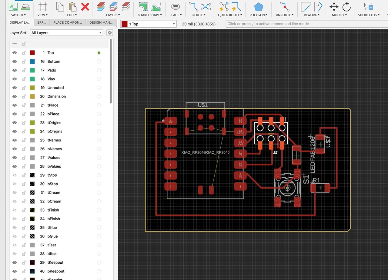
Check that your board complies with design principles (i.e. your wires are separated enough, your traces are thick enough, etc.)
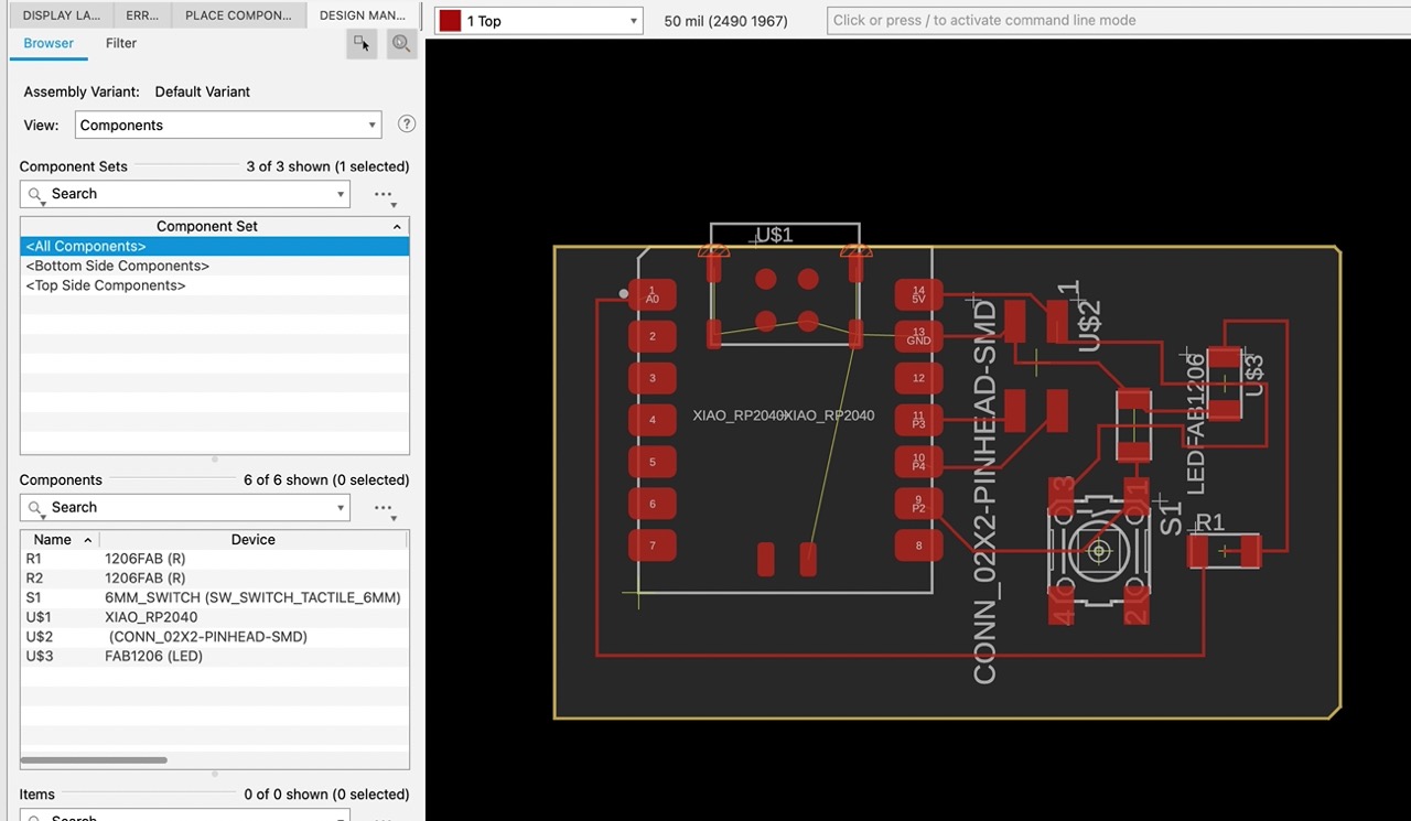
First step is PCB document which define relationship- Schematic / label what each pin is connected
There are a couple short cuts on Eagle in Fusion that helped check for compliance that I do not remember now
I ended up changing the type of connector I had to a 6 pin one so I can attach 3v and 5v devices to the board
I did not realize you can route the board through the middle of components underneath them
It's improtant to go back and forth between schematic and board to make sure everything is connected properly
Pre-Design Principles Board
Post-Design Principles Board
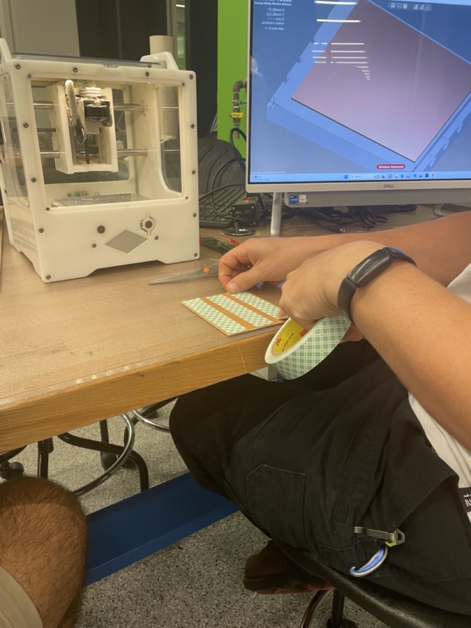
Circuit board milling
Upload schematic to usb drive using the right file extension - it may be based on what cnc mill you're gonna be using
Plug in design to machine - it will give you an estimate that is ballpark but not great and also you can optimize the path depending
on bit size
Besides changing bits you can also sometimes make double sided pcb boards
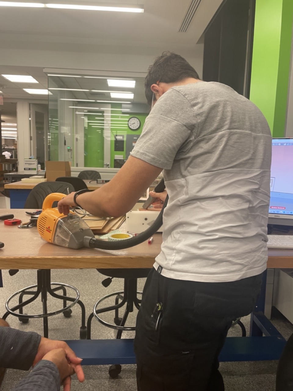
Sometimes the boards come out a bit fluffy
If you take like a metal putty like knife you can scrape at it and it comes out much cleaner - you should replace the bit
Basic board will take like 10 minutes to mill
Pre-Design Principles Board
Post-Design Principles Board
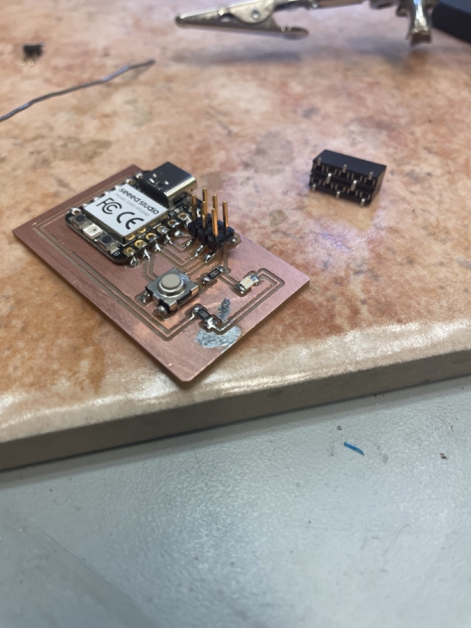
Circuit board soldering
Get a soldering station and put to like 700 degree farenheight - you can also use a heat gun sometimes but that I think is used for smaller components
Line your pieces up according to schematic and make sure you have the right orientation and part
I accidentally connected a two pin instead of a three pin to the 2x3 pads and had to improvise to fix
If you get unwanted solder on it you can wick it off no worries
Most importantly you want to test your board for shorts by setting the multimeter to continuity and touching the leads to the pins and different routes on the board
Pre-Design Principles Board
Circuit board programming
I uploaded micropython to arduino after plugging it in with boot button pressed
I used chatgpt to modifiy one of the base level example to work with pins in my board - specifically the button and the led
It changed my code so that everytime i press the button it turns the led rgb on and off
I had to change the pins to the ones I had on my board according to my schematic. Micropython on the datasheet is read as pins which
was good to know and you will have to read your datasheet to know how to reference the difference pins